SDF used to Deform Geometry
Animation of a Torus stamping footprints onto a grid by using SDF values to deform the grid and create footprints
In the previous post, I used the SDF to detect when two objects collide with each other or when objects overlap. Building upon that collision detection, we can also use the SDF to deform the object upon the collision.
Let’s setup a scenario where a Torus object is in direction collision with a ground plane and upon colliding, the Torus leaves a footprint deforming the ground plane. The ground plane gets deformed by the Torus, and the next step is to calculate the magnitude and direction of the deformation in order to generate the footprint and complete the animation.

Using the Negative SDF value to detect collision
Quoted from the last blog post:
“In Houdini, the SDF volume values of an object are negative if position is located inside the interior volume of an object. And positive if the P position is located away from the exterior surface of the object.”
Therefore in our scenario where the Torus is colliding with the ground plane, the result of comparing the SDF Volume value will be negative.

Displacing the Ground to create Footprints
The condition in the if node from the screenshot, will be satisfied. The condition is met and the operations inside the if node will execute (double click the if node to see the operations). The if node has a network inside itself, similar to VOP nodes, which contains a network of operations inside and will be revealed upon double clicking it.
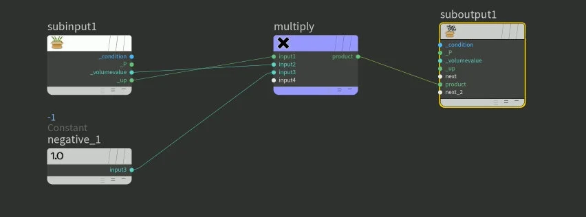
Node Network inside the if node
Upon double clicking the if node will reveal the network of operations like the screenshot on the right.

SDF value is the distance from the current P position to the surface of the Torus geometry
The _volumevalue parameter is the SDF value of the Torus.

Product of SDF and -1
The _volumevalue which is the SDF is being multiplied to -1. Remember from the previous blog post that the SDF value is a negative distance value. The distance is the distance from the location of position P to the surface of the Torus, basically how deep the torus is pressed onto the ground plane in this case. Now the SDF returns a negative SDF value because we are looking at the scenario when the Torus collides with the ground plane.
But in terms of the math, do we really need the negative SDF value?
We need the distance value for sure, but the negative value isn’t helping us calculate the footprint or how deep the footprint is pressing onto the ground plane. So, by multiplying -1 to the _volumevalue, which is the SDF volume value it becomes positive.
You can use the absolute function to achieve the same result instead of using the -1, because the -1 value is only there to negate the negative signed value of the SDF, since we’re only interested in the magnitude.
_volumevalue x -1= SDF value x -1= negative distance value x -1= distance (this is a positive value, because we only want the magnitude of the distance)Now we have magnitude of the distance and we have _P, which is the position value which is the positional value used to query the SDF and figure out whether the Torus is colliding with the ground plane in the first place. So we have magnitude and P, but we still don’t have direction.
The _up parameter is the up vector which provides direction.

By multiplying the up vector and the distance we got from the SDF value, we get the displacement value. This displacement has magnitude and direction, so we can use this in our vector calculation.
Vectors are mathematical objects that have both magnitude and direction. The displacement we have calculated can be treated as a vector.
Displacement is subtracted from P to create a
After getting the displacement value from the if node network, we take the P values from the grid and subtract it by the displacement value we got from the if node. We subtract the displacement values from P, because P is the position values from the grid and we are deforming the grid to create the footprint.

Deformed grid to create footprints
The displacement results in footprints depressed onto the grid. P position values on the grid are deformed and moved around by the subtracting the displacement value calculated from the if node network operations and using the SDF values.
Putting All the Knowledge Together with the SDF
The last three posts, including this post cover SDF values deforming geometry (this blog post), SDF values detecting collision, and animated sine wave motion. By putting all this together, you can create a very complex animation using simple techniques, like the SDF values. I admit at first, it may be overwhelming, but once you understand the fundamentals, I believe you will enjoy using the SDF in your animations or simulations.